Car diagnostic tools information by obd2tool
Welcome to my blog,here some auto diagnostic tools will be displayed. If you want to know more information,you can visit our official website: www.obd2tool.com.Car diagnostic tools information by obd2tool
Welcome to my blog,here some auto diagnostic tools will be displayed. If you want to know more information,you can visit our official website: www.obd2tool.com.Nissan Maxima 2012 ALL Keys Lost Autek ikey820 Add A New Key
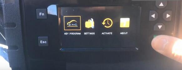
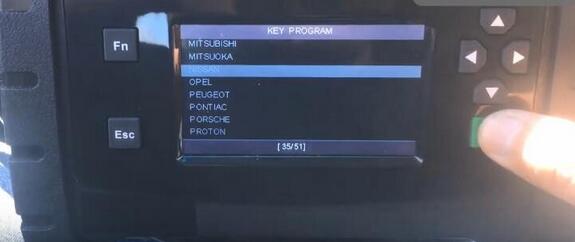
Here, we’re gonna to add a new key using Autek ikey820 on Nissan.
Purpose: key program
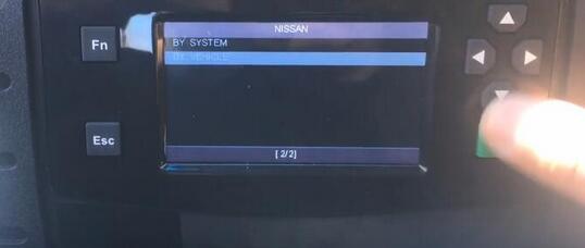
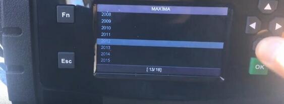
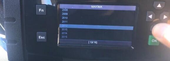
Car model and year: Nissan MAXIMA 2012
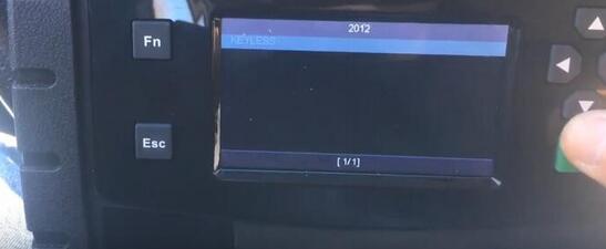
Key: keyless
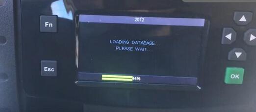
loading software
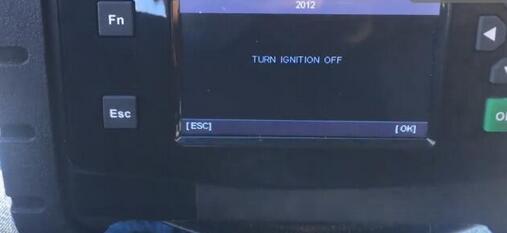
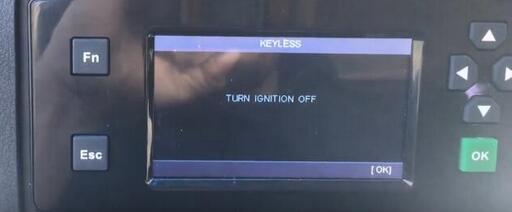
turn ignition off
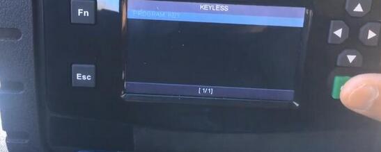
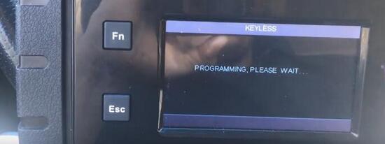
Autek starts to program a new key when all keys are lost
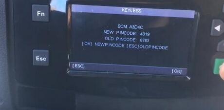
the new and old pin code
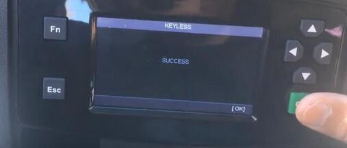
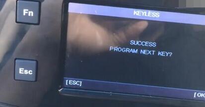
success!
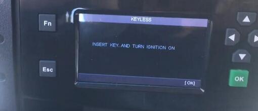
insert the key and turn ignition on

Autek ikey820 car key programmer is programing a new key…
turn ignition off

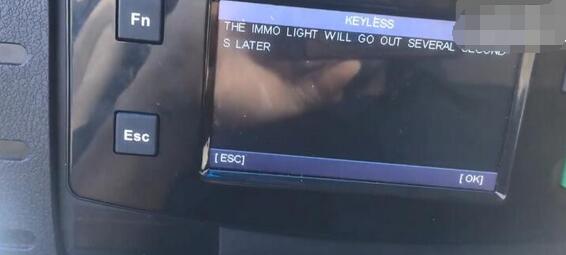
the immo light will go out in several seconds
success! ikey820 managed to program 12’ maxima key
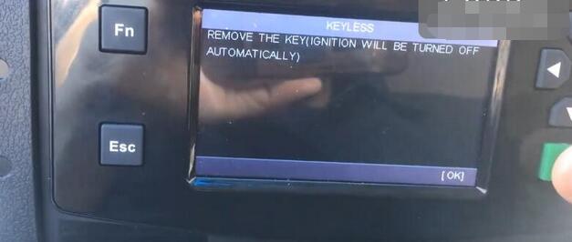
remove the key (ignition will be turned off automatically)


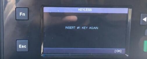
inster #1 key again
turn ignition on

remove the key (ignition will be turned off automatically)
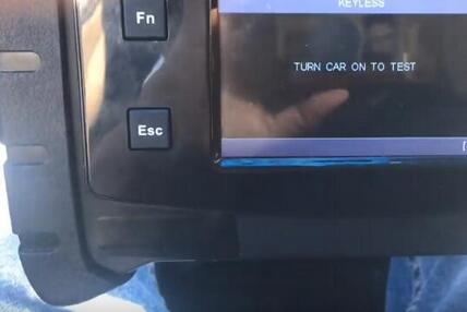
test the new key to see if it works or not

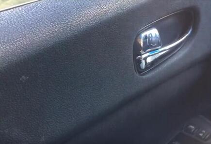

the new key is working good!
have a good success with iKey820!
How to do SPS or SPS Pass-Thru Programming with Tis2web ?
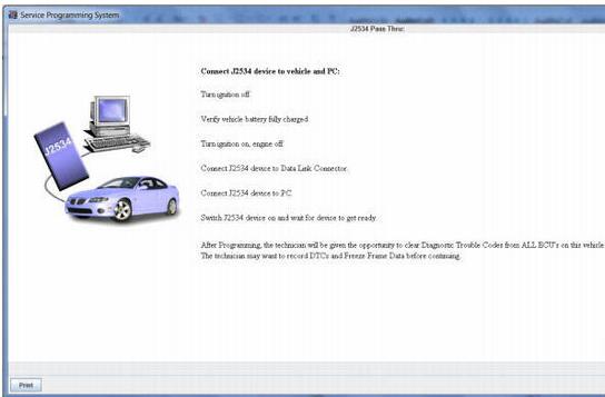
Important: SPS programming of vehicle controllers is not supported in GDS2. For SPS Pass Through programming with the J2534 interface tool, use the TIS2Web SPS application.
GDS2:
GDS2 is designed for use by trained service personnel to diagnose and repair automotive electronic systems. Every attempt has been made to provide complete and accurate technical information based on factory service information available at the time of publication. However, the right is reserved to make changes at any time without notice. To familiarize yourself with GDS2 and its capability, and how to use it, please read through the User’s Guide before putting the GDS2 to work.
GDS2 provides the following capabilities in multiple languages:
Read codes, code status, Freeze Frame data and Clear Codes.
Read VIN, ECU part numbers and software numbers.
Record, store and replay Stored data.
Control and monitor Output Control functions.
Configure and Reset functions.
Record or display history of the previous vehicle diagnostic sessions.
TIS has six major applications:
Software Download (SWDL)
Service Programming System (SPS)
Calibration Information (SPS Info)
Security Access (Security)
Snapshot (Snap)
Global Diagnostic System (GDS)

Depending on what access user profile you have and what region you are from, additional icons may appear.
Service Programming System (SPS)
The Service Programming System (SPS) updates the flash calibration files that are stored in a vehicle onboard controller (e.g. PCM, ABS, VTD). The calibration file custom-tailors a module to a certain vehicle. The calibration file contains data such as spark curves and fuel control. When troubleshooting a drivability condition, diagnosis may call for reprogramming the controller with newer calibration information to correct a customer concern.
The Service Programming System (SPS) updates the flash calibration files that are stored in a vehicle onboard controller (e.g. PCM, ABS, VTD). The calibration file custom-tailors a module to a certain vehicle. The calibration file contains data such as spark curves and fuel control. When troubleshooting a drivability condition, diagnosis may call for reprogramming the controller with newer calibration information to correct a customer concern.
Programming Tool Interface
The SPS application is part of the TIS2Web system. To program an ECU, the SPS application must communicate with the vehicle control modules using the proper J2534 programming interface tool. A Programming Interface tool is your connection between your computer and the vehicle’s J1962 DLC connector for pass-thru programming of the vehicle’s ECUs.
The following are the supported interface tools:
Tech2 scan tool
MDI interface
J2534 Programming Interface Tool
The following are four generally used types of serial communications used with an ECM/PCM controller:
UART (Universal Asynchronous Receive and Transmit)
Class 2
Keyword
GM LAN
Note: If your J2534 device has wireless capability, it is recommended to use the hardwired interface of the programming tool while programming an ECU.
Selecting the Correct Calibration
When reprogramming a vehicle, selecting the correct calibration is critical. You will only see calibrations that are valid for the VIN entered. Be sure to check the history of each calibration. The history lists an explanation of the calibration file, telling what the calibration is for and whether it supersedes any other calibrations. It is helpful to read the latest bulletins to stay up to date on why certain calibrations have been released. Related bulletin numbers are sometimes listed along with the calibration files.
Based on the calibration history and bulletins, select the appropriate calibration file. For many vehicles, you will also need to complete the multiple tab selections. Each tab is for a distinct calibration file. An unchecked box on a system tab indicates that a necessary selection has not been made.
If you need a VCI number, contact your Customer Support Center. Once you have the VCI number, it must be entered in the entry screen when requested by the SPS.
The general three-part process for SPS programming is as follows, regardless of the vehicle involved:
1.Check the vehicle’s control module to determine which, if any, calibration file is currently stored.
2.Determine if an update is required.
3.Transfer the selected data to the vehicle’s control module.
Caution: Prior to performing SPS, it is important to heed the following precautions:
1.Using an outdated version could damage vehicle modules. The J2534 interface tool and the terminal must have the latest software.
2.Make sure the vehicle battery is fully charged. Battery voltage for SPS should be between 12 and 14 volts. Due to the time requirements of programming a controller, connect a fully charged 12V jumper or booster pack disconnected from the AC voltage supply. DO NOT connect a regular battery charger.
3.Stable battery voltage is critical during programming. Any fluctuation, spiking, over voltage or loss of voltage will interrupt programming.
4.Make sure the cable connections are secure. A disconnected cable MAY cause controller failure.
5.In using a laptop computer/other display device (PDA etc.) for pass-thru programming, ensure that the power supply is properly connected. If powered by AC and the power cord becomes disconnected, it could interrupt programming and cause damage to the control module. If the laptop is operating from its internal power source (batteries), then make sure it is adequately charged to complete the SPS process.
Note: ECU to be programmed must be installed in the vehicle before beginning this process.
Performing Pass-Thru Programming
Pass-thru programming requires that the Scan Tool remain connected to the terminal and to the vehicle throughout the programming process. The vehicle must be in close proximity to the terminal while using pass-thru programming.
Note: TIS2Web only supports Pass-Thru Programming with the J2534 interface tool / Tech2.
Pass-Thru Programming Procedure
1.Connect a fully charged 12V jumper or booster pack disconnected from the AC voltage supply. DO NOT connect a regular battery charger.
2.Launch TIS2Web.
3.From the TIS2Web main screen, select the Service Programming System icon.
Power ON the scan tool.
Key on, battery fully charged.
Select “Start SPS”.
If hardware screen does not appear, check Tech2 hardware connections. This process could take some time depending upon your internet connection. You will be requested to perform an SPS software update, if one is required.

■Select Diagnostic Tool
■Select Programming Process
■Select Next

4.Connect the Scan Tool to the vehicle and computer. Select Next.

Note: You may receive a message that states: “Please restart your programming interface and press OK to retry: Press cancel to abort!” It is important to close all programs including TIS2Web when performing SPS to allow programming to continue.
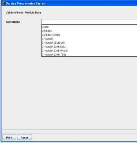
5.Select the Sales Make of the vehicle. Select Next.

6.You may or may not receive a pop-up screen. Ensure correct VIN is displayed. If VIN is incorrect or missing enter the correct. Select Next.
Note: In order to reduce the potential for signal loss, the J2534 interface tool should be configured for the most stable communication option at your location.
Note: The J2534 interface tool may have wireless capability, however it is recommended when using a programming interface tool to program an ECU that it is hardwired to the programming tool which contains the SPS application.

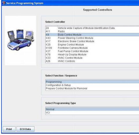
7.At the Supported Controllers screen:
Select the appropriate control module under “Select Controller”, e.g. PCM / VCM Control Module etc.
Select the appropriate programming type (Normal, VCI).
Select “Next” Note: For VCI programming you will need to contact the ACDelco Aftermarket Support Center.
8.During communication a “validate /select vehicle data” screen will appear. You may or may not get a pop-up screen.

9.At the Calibration Selection screen: Select the appropriate calibration(s).
Make sure all folder tabs have a green check mark.
Select “Next”.

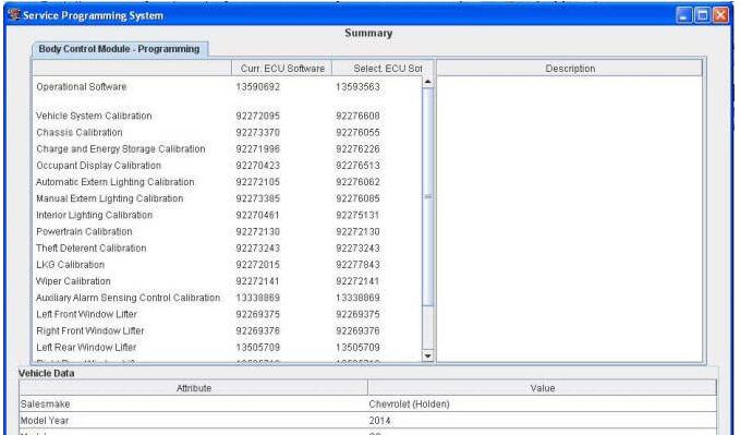
10.At the Summary screen: Verify current calibration(s) with selected calibration(s).
The current calibration is displayed along with the new calibrations available for the selected vehicle.
Note: If you are attempting to reprogram a vehicle with the same calibration, a pop up window will appear. In most cases reprogramming will not be required. Select Cancel to stop if reprogramming is not required, otherwise continue on with the procedure. General Motors does not recommend reprogramming with the same calibration.
Select “Next”.
Caution: To help avoid damage to the vehicle controllers, DO NOT turn the ignition off during a reprogramming event unless instructed to.

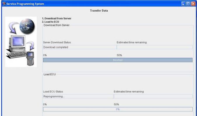
The Transfer Data screen appears as reprogramming begins, finishing when the percentage bar reaches 100 percent. Time may vary depending upon calibration. Estimated remaining programming time will appear on the screen.
11.The Program Controller “Programming Complete” screen appears.
A Warranty Claim code will appear if applicable.
A Warranty Claim Code is a 5 digit code which is unique for each programming event and is required to be documented on a submitted warranty claim.
12.Select “Clear DTCs” to erase history data. The program will return to the TIS2Web main screen. Be sure to verify successful reprogramming.
Note: DTCs may set during programming. Clear DTCs after programming is complete.
13.Turn off the Scan Tool. Select “Cancel”.
Note: Some vehicles will require that Idle Learn, TP Learn, Theft Deterrent Relearn, or Camshaft Variation Learn procedures be performed after programming. Consult the appropriate service information for these procedures.
14.Disconnect the GM Scan Tool from the vehicle.
How to use Tis2web for SPS or SPS Pass Thru programming
Important: SPS programming of vehicle controllers is not supported in GDS2. For SPS Pass Through programming with the J2534 interface tool, use the TIS2Web SPS application.
GDS2:
GDS2 is designed for use by trained service personnel to diagnose and
repair automotive electronic systems. Every attempt has been made to
provide complete and accurate technical information based on factory
service information available at the time of publication. However, the
right is reserved to make changes at any time without notice. To
familiarize yourself with GDS2 and its capability, and how to use it,
please read through the User’s Guide before putting the GDS2 to work.
GDS2 provides the following capabilities in multiple languages:
Read codes, code status, Freeze Frame data and Clear Codes.
Read VIN, ECU part numbers and software numbers.
Record, store and replay Stored data.
Control and monitor Output Control functions.
Configure and Reset functions.
Record or display history of the previous vehicle diagnostic sessions.
Tis2web:
TIS has six major applications:
Software Download (SWDL)
Service Programming System (SPS)
Calibration Information (SPS Info)
Security Access (Security)
Snapshot (Snap)
Global Diagnostic System (GDS)

Depending on what access user profile you have and what region you are from, additional icons may appear.
Service Programming System (SPS)
The Service Programming System (SPS) updates the flash calibration files that are stored in a vehicle onboard controller (e.g. PCM, ABS, VTD). The calibration file custom-tailors a module to a certain vehicle. The calibration file contains data such as spark curves and fuel control. When troubleshooting a drivability condition, diagnosis may call for reprogramming the controller with newer calibration information to correct a customer concern.
The Service Programming System (SPS) updates the flash calibration files that are stored in a vehicle onboard controller (e.g. PCM, ABS, VTD). The calibration file custom-tailors a module to a certain vehicle. The calibration file contains data such as spark curves and fuel control. When troubleshooting a drivability condition, diagnosis may call for reprogramming the controller with newer calibration information to correct a customer concern.
Programming Tool Interface
The SPS application is part of the TIS2Web system. To program an ECU, the SPS application must communicate with the vehicle control modules using the proper J2534 programming interface tool. A Programming Interface tool is your connection between your computer and the vehicle’s J1962 DLC connector for pass-thru programming of the vehicle’s ECUs.
The following are the supported interface tools:
Tech2 Scan Tool
MDI interface
J2534 Programming Interface Tool
The following are four generally used types of serial communications used with an ECM/PCM controller:
UART (Universal Asynchronous Receive and Transmit)
Class 2
Keyword
GM LAN
Note: If your J2534 device has wireless capability, it is recommended to use the hardwired interface of the programming tool while programming an ECU.
Selecting the Correct Calibration
When reprogramming a vehicle, selecting the correct calibration is critical. You will only see calibrations that are valid for the VIN entered. Be sure to check the history of each calibration. The history lists an explanation of the calibration file, telling what the calibration is for and whether it supersedes any other calibrations. It is helpful to read the latest bulletins to stay up to date on why certain calibrations have been released. Related bulletin numbers are sometimes listed along with the calibration files.
Based on the calibration history and bulletins, select the appropriate calibration file. For many vehicles, you will also need to complete the multiple tab selections. Each tab is for a distinct calibration file. An unchecked box on a system tab indicates that a necessary selection has not been made.
If you need a VCI number, contact your Customer Support Center. Once you have the VCI number, it must be entered in the entry screen when requested by the SPS.
The general three-part process for SPS programming is as follows, regardless of the vehicle involved:
Check the vehicle’s control module to determine which, if any, calibration file is currently stored.
Determine if an update is required.
Transfer the selected data to the vehicle’s control module.
Caution: Prior to performing SPS, it is important to heed the following precautions:
Using an outdated version could damage vehicle modules. The J2534 interface tool and the terminal must have the latest software.
Make sure the vehicle battery is fully charged. Battery voltage for SPS
should be between 12 and 14 volts. Due to the time requirements of
programming a controller, connect a fully charged 12V jumper or booster
pack disconnected from the AC voltage supply. DO NOT connect a regular
battery charger.
Stable battery voltage is critical during programming. Any fluctuation,
spiking, over voltage or loss of voltage will interrupt programming.
Make sure the cable connections are secure. A disconnected cable MAY cause controller failure.
In using a laptop computer/other display device (PDA etc.) for pass-thru
programming, ensure that the power supply is properly connected. If
powered by AC and the power cord becomes disconnected, it could
interrupt programming and cause damage to the control module. If the
laptop is operating from its internal power source (batteries), then
make sure it is adequately charged to complete the SPS process.
Note: ECU to be programmed must be installed in the vehicle before beginning this process.
Performing Pass-Thru Programming
Pass-thru programming requires that the Scan Tool remain connected to the terminal and to the vehicle throughout the programming process. The vehicle must be in close proximity to the terminal while using pass-thru programming.
Note: TIS2Web only supports Pass-Thru Programming with the J2534 interface tool / Tech2.
Pass-Thru Programming Procedure
Connect a fully charged 12V jumper or booster pack disconnected from
the AC voltage supply. DO NOT connect a regular battery charger.
Launch TIS2Web.
From the TIS2Web main screen, select the Service Programming System icon.
Power ON the scan tool.
Key on, battery fully charged.
Select “Start SPS”.
If hardware screen does not appear, check Tech2 hardware connections.
This process could take some time depending upon your internet
connection. You will be requested to perform an SPS software update, if
one is required.

Select Diagnostic Tool
Select Programming Process
Select Next
Connect the Best obd2 scanner to the vehicle and computer. Select Next.
Note: You may receive a message that states: “Please restart your programming interface and press OK to retry: Press cancel to abort!” It is important to close all programs including TIS2Web when performing SPS to allow programming to continue.
Select the Sales Make of the vehicle. Select Next.
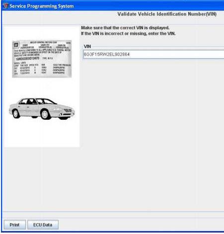
You may or may not receive a pop-up screen. Ensure correct VIN is displayed. If VIN is incorrect or missing enter the correct. Select Next.
Note: In order to reduce the potential for signal loss, the J2534 interface tool should be configured for the most stable communication option at your location.
Note: The J2534 interface tool may have wireless capability, however it is recommended when using a programming interface tool to program an ECU that it is hardwired to the programming tool which contains the SPS application.
At the Supported Controllers screen:
Select the appropriate control module under “Select Controller”, e.g. PCM / VCM Control Module etc.
Select the appropriate programming type (Normal, VCI).
Select “Next” Note: For VCI programming you will need to contact the ACDelco Aftermarket Support Center.
During communication a “validate /select vehicle data” screen will appear. You may or may not get a pop-up screen.
At the Calibration Selection screen: Select the appropriate calibration(s).
Make sure all folder tabs have a green check mark.
Select “Next”.
At the Summary screen: Verify current calibration(s) with selected calibration(s).
The current calibration is displayed along with the new calibrations available for the selected vehicle.
Note: If you are attempting to reprogram a vehicle with the same calibration, a pop up window will appear. In most cases reprogramming will not be required. Select Cancel to stop if reprogramming is not required, otherwise continue on with the procedure. General Motors does not recommend reprogramming with the same calibration.
Select “Next”.
Caution: To help avoid damage to the vehicle controllers, DO NOT turn the ignition off during a reprogramming event unless instructed to.

The Transfer Data screen appears as reprogramming begins, finishing when
the percentage bar reaches 100?percent. Time may vary depending upon
calibration. Estimated remaining programming time will appear on the
screen.
The Program Controller “Programming Complete” screen appears.
A Warranty Claim code will appear if applicable.
A Warranty Claim Code is a 5 digit code which is unique for each programming event and is required to be documented on a submitted warranty claim.
Select “Clear DTCs” to erase history data. The program will return to the TIS2Web main screen. Be sure to verify successful reprogramming.
Note: DTCs may set during programming. Clear DTCs after programming is complete.
Turn off the Scan Tool. Select “Cancel”.
Note: Some vehicles will require that Idle Learn, TP Learn, Theft Deterrent Relearn, or Camshaft Variation Learn procedures be performed after programming. Consult the appropriate service information for these procedures.
Disconnect the GM Scan Tool from the vehicle.
What is tech2?
What is tech2?
The Tech 2 is a powerful, versatile hand-held diagnostic computer, designed to help diagnose and repair today’s automotive electronic systems. The Tech 2 supports the changes in the on-board electronic systems for model years 1996 and beyond. With the addition of the CAN Diagnostic Interface (CANdi) module, Tech 2 will support GM on-board electronic systems for years to come.
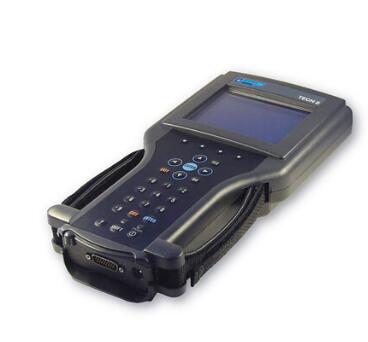
The CANdi is an in-cable module that works with existing Tech 2 components including the VCI, cables and adapters to add CAN diagnostic capability to the Tech 2 tester. The CANdi module is fully backward compatible with current Tech 2 functionality and operates transparently when diagnosing non-CAN-equipped vehicles.
The Tech 2 provides extensive diagnostic capability through the 32MB PCMCIA card. The PCMCIA card stores diagnostic information intended to diagnose powertrain, body or chassis control modules and related vehicle malfunctions. It also contains the Service Programming System (SPS) application which allows the Tech 2 to program control modules with vehicle calibration data.
The PCMCIA card is updated by linking the Tech 2 to a PC that has access to the ACDelco TDS website. This method of communication provides flexibility for updating the card with vehicle calibration data, mid-year and new-model-year vehicle diagnostics and Tech 2 software enhancements. Software updates are distributed to GM dealers automatically via TIS2WEB at the GM Global Connect web site or go directly to the TIS2WEB site to download updates at any time.
The Tech 2 is capable of capturing a snapshot of vital performance
data at idle or during a test drive. You can replay the snapshot or plot
and graph the data directly on the Tech 2, or the snapshot file may be
uploaded to an approved GM Techline terminal. The file may also be
stored on the CD-ROM terminal for future reference. The snapshot
capability allows you to see where an intermittent fault occurred, even
if it did not set a trouble code.
Model Year Coverage
92 up OBD systems CAN equipped vehicle coverage with CANdi module
PC Requirements:
Only required if reprogramming or Tech 2 diagnostic software update
is performed. Tech 2 is a stand-alone diagnostic tool. Currently GM is
recommending a minimum Intel i5 processor
Recommended package:
Intel Core i5 at 2.6GHz 64 bit
2) USB 2.0 (or better) ports
500GB Hard drive
4GB ram
Windows 7 Professional 64bit
Internet Explorer 9 +
Wireless capability
Note: The Tech 2 uses a legacy DB9 Serial Null modem cable to connect to
PC. Current spec PC do not have this connection. It will be necessary
to have the null modem cable and a Tripplite Serial to USB adapter
properly configured on the machine to perform reprogramming or
diagnostic software updates.
Software License
Available as three different subscriptions:
Complete GM Service Support Package Includes: GM SI, Tis2Web – All Access, GDS 2, and Tech2Win
Tech 2 Service and programming package which includes software updates
and license for the Tech 2 operating software, Service programming
software, Tech 2 View, Tech 2 Snap Shot, and Tech2Win
Tech 2 Diagnostics Includes: Car Diagnostic Tool Tech 2 Diagnostic software updates
The Tech 2 does not time out if the software becomes outdated. The tool will display a message to update as a reminder and may not operate correctly with newer vehicles if it is not updated regularly.
2010 Benz S550 error “Air Suspension malfunction” solution
Topic: How-To solve the error that 2010 Benz S550 got ” Air Suspension malfunction”. MB diagnostics like MB SD Connect C5 /Star C4 will play its role.
What to do:
need to have someone check for fault codes using MB diagnostics like MB sd connect C5 /C4 while doing so also re-calibrate suspension. DIY – check all sensors/connections, revisit struts and control valve for connection problems/leaks, check compressor harness/connection. Worst case scenario possible strut internal leakage in which case it would need to be replaced.
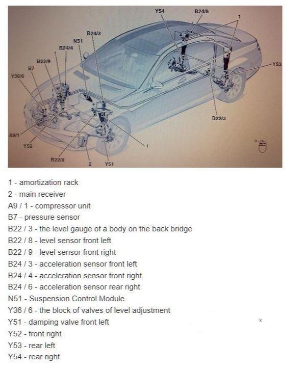
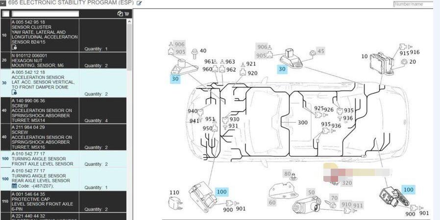
Suspension strut component description
Check AIRmatic for leaks
Here comes one question:
One question I have is around Y36/6, I don’t see that in my vehicle or at least not in that layout. If I look at the closeup of the Y36/6 in the attached document, it does not match what I see in the picture below, in the attachment/closeup I see 6 white rubber/plastic tubes coming out and the location is color coded but if you look at the picture y36/6 has 4 metal tubes coming out on the side, is it because the closeup is shown after a cover has been removed?
Also, on mine, on top of the compressor there is a silver metallic block that has 4 metal tubes coming out from the top and not from the sides, is the difference due to mine not being 4Matic?
Last but not the least, all the diag and re-calibration you talk about, can those be done through MB STAR Tool?
Here is the answer:
4matic does not matter, Y36/6 is the valve block @ compressor only thing that might appear different is labeling could be missing. STAR should accommodate re-calibration & diagnostics.

install air suspension valve unit
install compressor
install bottom engine compartment paneling
Finally, I purchased Benz C5 with SD disk, here is the link.
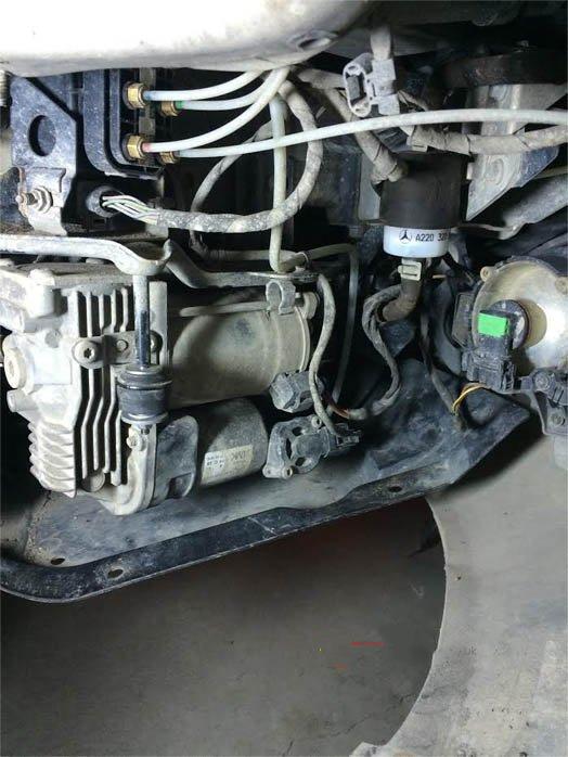
Compressor and valve unit are behind the bumper just in front of the right wheel. If you remove the right front wheel and the wheel well liner you will see the valve block.
Here’s the pic for quick reference
What’s the deal with jacking the car?
I typically follow the WIS procedures. For the suspension work you would normally want to release pressure from the struts in order to avoid damage to them or you. I’ve always done this via Xentry.
What type of lug?
After finally understanding how to locate and test the air leak at the valve, it turns out my wheels have special lugs all of them as opposed to one being the lock nut. It looks like flower, what gives??? I only have the usual MM impact wrench socket. What is it called and where to get it?
Reply: So, 17mm has been stock on many Mercedes for some time. The Convex (flower head) bolts appeared with the Maybach and then the W221 and are also on several other models. It is entirely possible that someone put 17mm hex head bolts on your car or even another size, do you have aftermarket wheels? You might just take a 17mm, 18mm, 19mm, etc. out to the car with you to see which one fits best. At the very least the lug wrench in the tool kit in the trunk should fit.
I fixed my Airmatic issues Friday, so relieved.
I replaced the valve block (which I suspect was actually fine) and as I was putting the lines back in, I noticed a very small crack on one of the strut air lines where it must have been bent around the brass fitting. I cut off the bad inch and reconnected the line to the fitting, and now the suspension works just fine. I drove it for 7 hours yesterday (road trip) and not a single problem manifested itself! I did a soapy water leak test but this must have been too small to see.
Regarding that additional pump/component in the fender: I was able to take off the torx bolts holding it to the bracket there and slide the part over to the right. It actually fit pretty nicely just resting on the bottom of the FR fender/bumper. Anyways, just sliding it out of the way gave me enough room to work on the valve block.
Basic steps:
Removed wheel and wheel fender liner
Removed 2 torx bolts holding that mystery part on then carefully slid it off the bracket and braced it against the bumper/fender. Be very careful not to mess with the pressure lines too much, I’m not sure how much flexing they’re rated for but it certainly isn’t much.
Use a 10 mm wrench to crack open all the fittings at the valve block and drain the air system (compressor fitting uses a 12 mm)
Unscrew the single screw holding the valve body on and then slide the whole thing out, vehicle right. A rubber fitting holds it on the other end, it just slides off
If you have the same problem, you might as well get the valve body JIC… and follow the video instructions.