By establishing a data link to the electronic control systems
of the vehicle being serviced through the VCI device, the Diagnostics
application allows you to retrieve diagnostic information, view live
data parameters, and perform active tests. The OBD2 Scanner
application can access the electronic control module (ECM) for various
vehicle control systems, such as engine, transmission, antilock brake
system (ABS), airbag system (SRS) and more.
Establishing Vehicle Communication
The Diagnostics operations require connecting the Autel Maxisys Elite
Diagnostic Platform to the test vehicle through the VCI device using
the main cable, and test adapters (for non-OBD II vehicles). To
establish proper vehicle communication to the MaxiSys display tablet,
you need to perform the following steps:
1. Connect the VCI device to the vehicle’s DLC for both communication and power source.
2. Connect the VCI device to the MaxiSys dispvlay tablet via BT pairing, USB connection, or Ethernet connection.
3. When these are done, check the VCI navigation button at the bottom
bar on the screen, if the button displays a green tick icon at the lower
right corner, the MaxiSys Elite diagnostic platform is ready to start
vehicle diagnosis.
Vehicle Connection
The method used to connect the VCI device to a vehicle’s DLC depends on the vehicle’s configuration as follows:
1 A vehicle equipped with an On-board Diagnostics Two (OBD II)
management system supplies both communication and 12-volt power through a
standardized J-1962 DLC.
2 A vehicle not equipped with an OBD II management system supplies
communication through a DLC connection, and in some cases supplies
12-volt power through the cigarette lighter receptacle or a connection to the vehicle battery
OBD II Vehicle Connection
This type of connection only requires the main cable without any additional adapter.
To connect to an OBD II vehicle
1. Connect the main cable’s female adapter to the Vehicle Data
Connector on the VCI device, and tighten the captive screws.
2. Connect the cable’s 16-pin male adapter to the vehicle’s DLC, which
is generally located under the vehicle dash.
Non-OBD II Vehicle Connection
This type of connection requires both the main cable and a required OBD I adapter for the specific vehicle being serviced.
There are three possible conditions for Non-OBD II vehicle connection:
1 DLC connection supplies both communication and power.
2 DLC connection supplies communication and power is to be supplied via the cigarette lighter connection.
3 DLC connection supplies communication and power is to be supplied via connection to the vehicle battery.
To connect to a Non-OBD II Vehicle
1. Connect the main cable’s female adapter to the Vehicle Data Connector on the Autel Scanner, and tighten the captive screws.
2. Locate the required OBD I adapter and connect its 16-pin jack to the main cable’s male adapter.
3. Connect the attached OBD I adapter to the vehicle’s DLC.
To connect the cigarette lighter
1. Plug the DC power connector of the cigarette lighter into the DC power supply input port on the device.
2. Connect the male connector of the cigarette lighter into the vehicle’s cigarette lighter receptacle.
To connect the clipper cable
1. Connect the tubular plug of the clipper cable to the male connector of the cigarette lighter.
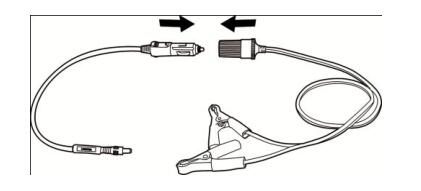
2. Plug the DC power connector of the cigarette lighter into the DC power supply input port of the J2534 programming device.
3. Connect the clipper cable to the vehicle’s battery.